BATHYMETRY |

The bathymetry is the study of the morphology of the seabed. Several echosounder exist, and
their uses are depending of what you want to “see”.
Two family of echosounders are used to do bathymetry:
The singlebeam and the multibeam.
To do a bathymetric chart, you do parallel and perpendicular profiles spaced of 5 to 10m at the maximum speed of 5 knots.
Your result (after data processing and modelling) is a bathymetric chart where you will find the informations of general trend and morphology of the area surveyed. The more you do profiles the more “real” is your bathymetric model.
This technic is good when the area to survey is small, or with shallow water or small place with difficulty in maneuvering (like in a harbour). It is also the cheapest method.
The material that is used for bathymetric sounding is a HYDROTRAC single beam echo sounder of the ODOM mark at high frequency (200 KHz). This echosounder allows both a paper record and a digital record of the data. Its characteristics are given in the data sheets presented in Appendix 1.
The sonar vertical calibration is performed before and after each intervention and following complementary and different methods depending on the configuration of the operation sites:
The accuracy of a topographic and bathymetric survey is very strongly related to the positioning system used to locate in the 3 dimensions of the space. The most commonly used positioning system today is Global Positioning System (GPS), which achieves a theoretical accuracy of about 5 to 10 m at the earth’s surface. The acquisition of so-called differential corrections provided by satellites or by ground beacons increases the accuracy of the system which is then metric or sub-metric. These GPS or differential GPS systems are however not usable in the context of topographic surveys where one seeks a precision of the order of 1 cm in the 3 dimensions of the space. The positioning tool used for the topography and the bathymetry that we have, allows to reach this centimetric precision. This is a TRIMBLE 5700/5800 real-time cinematic GPS station (DGPS / RTK). This equipment is a complete, truly integrated system consisting of two GPS (a 5700 base and a 5800 mobile), Pacific Crest, an ACU survey controller, and a desktop software. Trimble Geomatic Office). The data sheets for these devices are provided in Appendix 1.
The fundamental concept of DGPS / RTK technology is the use of a GPS receiver which is placed at a known position (base) and which sends position corrections to another GPS (mobile).
The centimeter calibration of the GPS 5700 base is established on or from the geodetic points of the French Base Network (RBF) or the French Reference Network (RRF) determined by the National Geographic Institute (IGN) for the use of the system. DGPS / RTK. The position of the base can also be calculated from the GPS stations that are part of the permanent network RGP managed by the IGN.
The material we use is a very powerful DGPS. It is composed of a GPS antenna allowing performance measurements of less than one meter (centimeter to decimetre), thanks to the differential corrections emitted by the IALA beacons (International Association of Marine Aids to Navigation and Lighthouse Authority) that it receives in real time. .
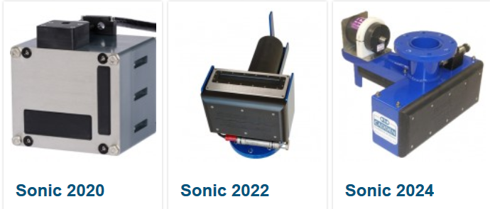
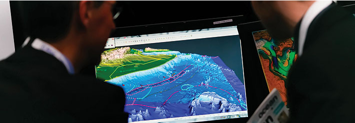
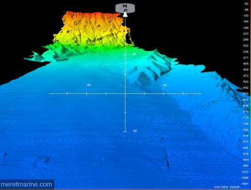
Today, Oceanlab is about to purchase high quality multi-beam equipment, namely the sonic multibeam sounder SONIC 2022 manufactured at Cadden (www.cadden.fr) allowing high precision work for multiple applications.
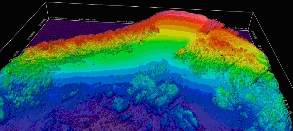
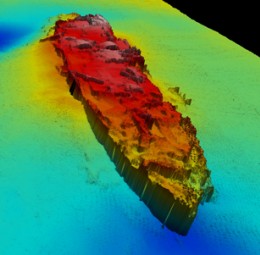
Image bathymetrique (à gauche) et image d’une epave (à droite) données par le sondeur multi faisceaux sonic 2022
www.cadden.fr